How to prevent and stop extruder vent flow

By Dean Elliott
Technical processing manager, Entek
There are five main processing limitations to increased throughput for a co-rotating twin-screw extruder: power, volume, shear, pressure and moisture. A sixth limitation known as vent flow is sometimes a line operator’s toughest challenge.
Vent flow is mostly caused by three of the five main limitations — pressure, moisture or volume — however, at times it cannot be traced to any of the five main limitations, earning its independence as a sixth processing limitation.
Vent flow occurs when polymer or compound flows out of a vacuum or atmospheric vent opening, preventing air and gases from escaping the extruder. Not only can vent flow cause product defects, it can create an undesirable mess.
Using a wood or plastic tool to clear out a vent is highly recommended. There are many examples of less-experienced operators who have used steel screwdrivers, prybars or scrapers to clear out a vent opening. Unfortunately, the outcome can potentially be catastrophic and extremely expensive when the metal tool is pulled into the extruder by the rotating screws.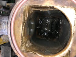
Understanding when a vent is vulnerable to vent flow and what causes vent flow is key to managing, minimizing or mitigating it. Below are factors that make a vent vulnerable to vent flow and possible corrective actions.
1. When it is located near the exit of the extruder and the die or exit pressure is high. A “high” exit pressure is not a standard pressure that all extruder operators avoid exceeding. A “high” pressure for one extrusion process is not necessarily the same for another because of the influence of multiple process variables, for instance, compound formula; polymer/compound viscosity; screw and barrel configuration; screw and barrel wear; throughput rate; screw speed; filtration screen mesh size and die hole diameter. In order to minimize or mitigate vulnerability to vent flow at a vent located near the exit end of the extruder, one should consider the following actions:
- Increase extruder screw speed to reduce the fill level of the extruder and improve pumping efficacy.
- Lower feeder throughput to reduce the fill of the extruder and reduce exit pressure.
- Replace worn screws and barrels downstream of the vent to improve extruder pumping efficacy.
- Alter the pitch of the convey screw elements downstream of the vent to one diameter pitch elements; in other words, for a 70mm diameter extruder, the pitch would also need to be 70mm.
- Alter the pitch of the convey screw elements under the vent to one diameter pitch elements.
- If possible, increase the mesh size of filtration screens to reduce exit pressure.
- Increase the diameter of die holes and/or add more die holes to reduce the exit restriction, which lowers exit pressure (die hole diameter has a far greater impact than the number of die holes).
- For underwater pelletizing, purge out frozen die holes to reduce the exit pressure. Also, if possible, raise the temperature of the water to reduce exit pressure and minimize the risk of freezing die holes.
- Increase the temperature of the die, adaptors and/or exit barrels to reduce exit pressure.
- For a vacuum vent, lower the level of vacuum.
2. When an atmospheric or vacuum vent is located upstream of and near a “restrictive” mixing element — for example, a reverse conveying element, a reverse kneading block or a neutral kneading block. Consider the following actions:
- Increase extruder screw speed to reduce the fill of the extruder and improve pumping efficacy.
- Lower feeder throughput to reduce the fill of the extruder.
- Replace worn screws and barrels downstream of the vent to improve extruder pumping efficacy.
- Alter the pitch of the convey screw elements downstream of the vent to one diameter pitch elements.
- Alter the pitch of the convey screw elements under the vent to one diameter pitch elements.
- If possible, alter the screw configuration and move the restrictive mixing elements further downstream from the vent.
- For a vacuum vent, lower the level of vacuum.
3. When a formulation is altered during a production run, causing a reduction in viscosity. Consider the following actions:
- Increase extruder screw speed prior to the formulation change to reduce the fill of the extruder and improve pumping efficacy. Restore initial extruder screw speed after the transition.
- Lower feeder throughput to reduce the fill of the extruder prior to the formulation change. Restore initial throughput after the change.
- If possible, assign someone to monitor the vent during the formulation change.
- Divert to purge during transition to reduce exit pressure.
4. When the feed system is unstable, compound viscosity changes occur. Consider the following actions:
- Increase extruder screw speed as soon as possible to reduce the fill of the extruder and improve pumping efficacy. Restore initial extruder screw speed after the feed system has stabilized.
- Lower feeder throughput as soon as possible to reduce the fill of the extruder. Restore initial feeder throughput after the feed system has stabilized.
- If possible, immediately assign someone to monitor the vent.
- Recalibrate feeders and/or reloading system.
- Alter feeder screw and/or tube.
5. When starting the extruder, residual material may act as a restriction along with typical start-up instabilities and viscosity changes. Consider the following actions:
- Start the extruder at a higher than targeted screw speed to minimize the fill of the extruder and improve pumping efficacy. Reduce screw speed to the target after the extruder has stabilized.
- Start the extruder at a lower than targeted feeder throughput to reduce the fill of the extruder. Increase to the target throughput after the extruder has stabilized.
- If possible, assign someone to monitor the vent during start-up.
- Purge out residual material/compound before product changeover.
6. When extruder torque suddenly rises significantly or is consistently high, this can be an indication that the fill level of the extruder is high. Consider the following actions:
- Increase the screw speed of the extruder to reduce the fill level and torque.
- Reduce feeder throughput to decrease the fill of the extruder.
- Confirm feeder and feeder refill settings are adequate.
- If possible, assign someone to monitor the vent while a high-torque situation is being brought under control by the operator.
7. When raising feeder throughput to the extruder without increasing the extruder screw speed, the fill level of the extruder rises. Consider the following actions:
- Raise the extruder screw speed along with feeder throughput to maintain specific throughput (throughput divided by screw speed).
- If possible, assign someone to monitor the vent while the feeder throughput is being increased.
8. When vent inserts are poorly designed or incorrectly installed. Consider the following:
- Whether the vent opening is located above the correct screw. It needs to be above the screw side that is rotating downward versus the screw side that is rotating upward.
- Whether the vent insert is bolted down evenly with equal torque applied to each bolt.
- Whether the design of the insert can inhibit or promote vent flow. There are many different vent designs.
- Increased understanding of what causes vent flow and when the extrusion system is vulnerable to it equips the operator to either prevent or rapidly respond to a vent-flow situation.
- Another option to help minimize vent flow is adding vent stuffers at vent openings. Vent stuffers act like a pump, preventing the polymer or compound from escaping the extruder while, allowing volatiles to escape.
An operator with a clear or better understanding of what causes vent flow and when the extrusion system is vulnerable to vent flow will either prevent or provide a rapid response to a vent flow situation. Running a lower vacuum for a given compound to prevent vent flow may not always be an option. Installing a vent stuffer allows higher vacuum draw, vent stuffers act like a pump preventing the polymer/compound from escaping the extruder while allowing volatiles to escape.

For more information:
Entek Extruders, Lebanon, Ore., 541-259-1068, www.entek.com.